Friday, April 25, 2014

Week 5

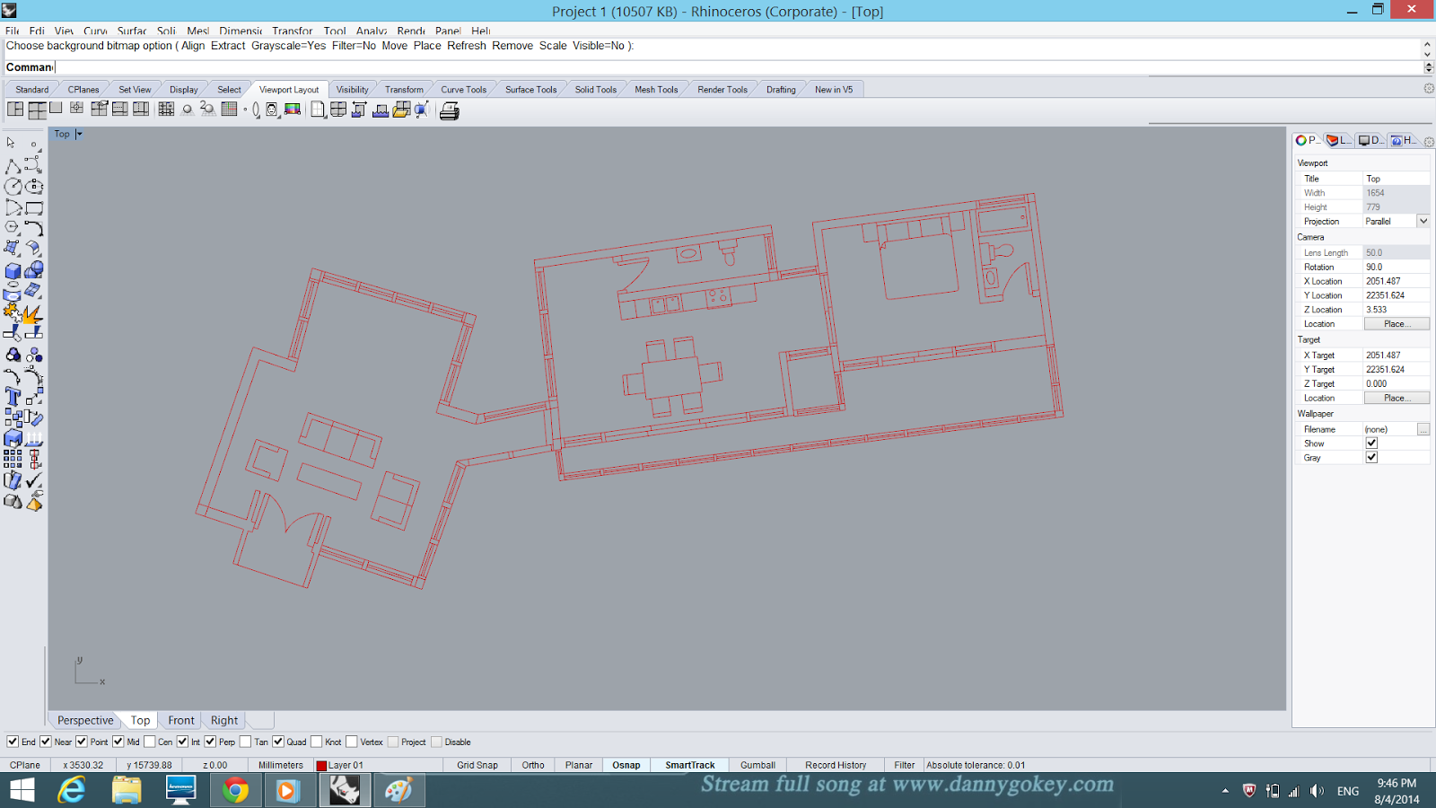
As I continued my progress since last week, I started tracing my first floor plan so that I can placed in on top of my ground floor building. Below is the picture of my first floor plan.


Then, I extruded the wall and windows as usual. When I was done with that, I started cutting the walls so that I can place my roof on it. I used the same method that I tried before (shown in week 4 WIP) to cut the wall.


 This is how it looks like after I cut the wall.


I encounter some difficulties when I was doing the roof for the protruding part. I tried to extruding the roof but it will go to different direction. Thus I found out that I can actually extend the roof by clicking "Extend Surface" but there is one line on the roof which makes it not that aesthetic. I will figure out how to delete that line after I m done extruding all the walls.


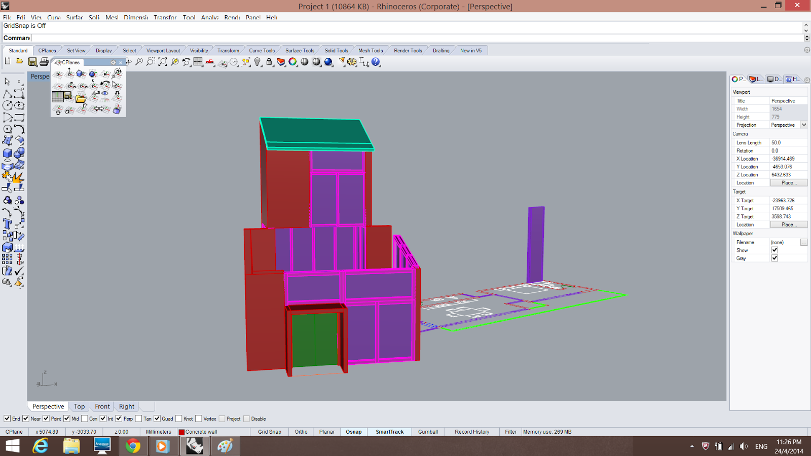
This is a picture of roughly how it looks like when it it place on top of the building.


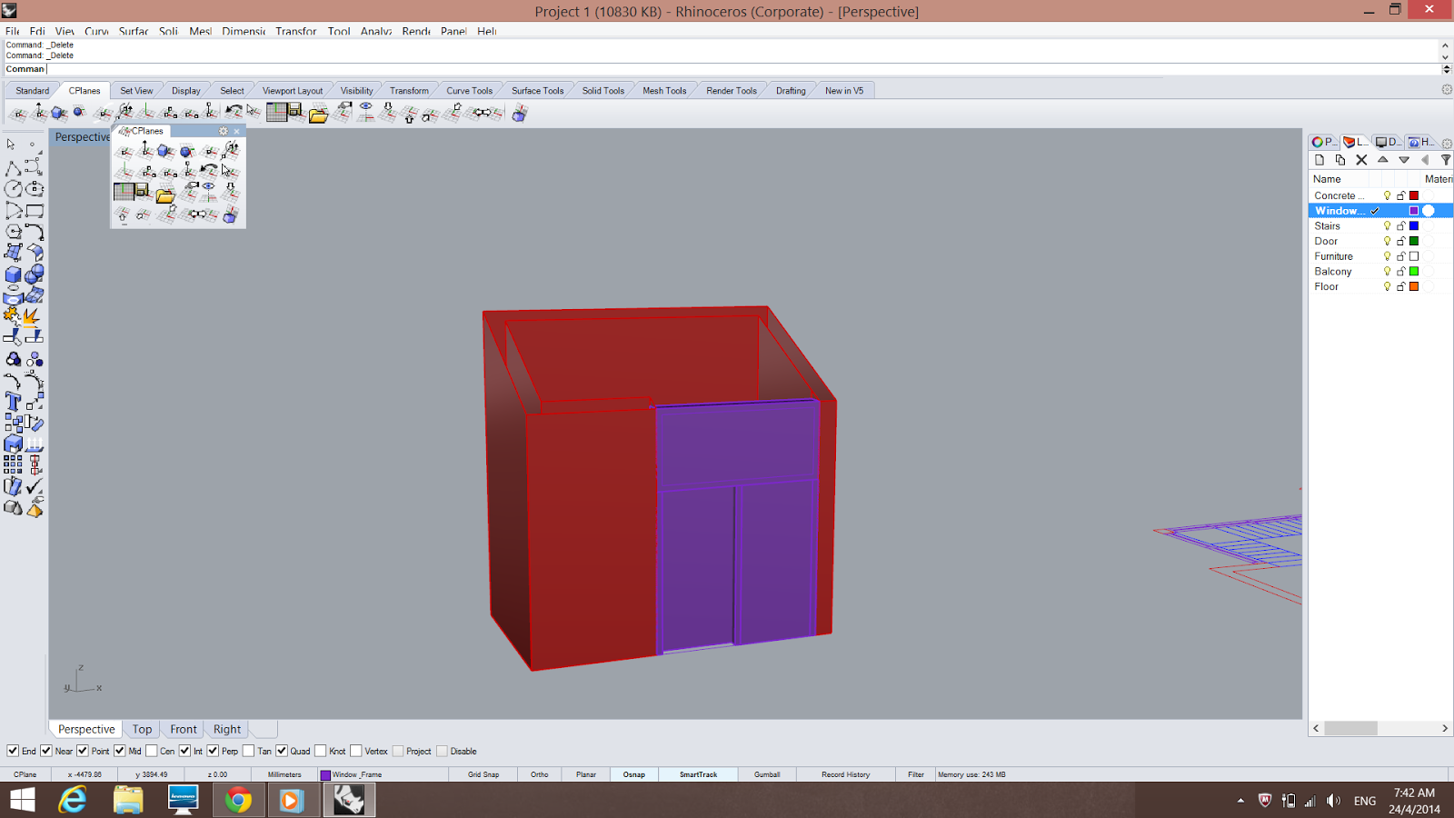
Next, creating the windows and frames took a longer time as I need to do it one by one. I have to ungroup all my windows and frames and group them separately. First of all, I extruded the window frames ( Left and Right) on both sides of the window. Then, I extruded the window glass. Followed by extruding the window frame on the bottom of the window glass and finally copy and paste it on the top of the window glass. 


Here is a picture on how I copied and paste the window frames.


 And this is how I cut the windows by using the extruding and splitting method.


An overview of the first part of the building.


Moving on, I continued using the same method to do the other parts of the building.


The second block of the the building before I cut the wall to place the roof.

This is how I did the slanted window frames by clicking the " Surface" icon and join the edges together to form a surface.


Here are some pictures of my progress.


Finally, here is a picture of what I have done for this entire week. 

Friday, April 18, 2014

Week 4

After tracing the entire ground floor plan of the building, I started to layer the lines so that it will be easier for me when I extrude the lines. I used different colours to represent different materials.For example, red for concrete wall, purple for windows frame, white for furniture,etc.
 The picture above shows the process of me completing the layering.


 How it looks like in perspective view.


After finishing the layering part, I started to extrude to walls of the building. At first, I extruded the walls but I forgot to change the colours of different parts of the building. Thus I deleted some of the walls and redo it.

 This is how it looks like when I did not change the colour.


Next, I wanted to change the height of the wall as my walls are in different heights so I drew a line so that I can extrude and split and then cut the excess walls. I encounter some problems when I was drawing the lines. Nevertheless, I managed to solve the problem but in a longer time.
 A picture of the line I drew to cut the walls.


 Another picture but different angle.

Then, I extruded the line so that there will be a surface for me to split the walls. In order to do that, I changed the C plane direction to the direction that I wanted. So, the line now can be extruded in the correct direction (surface facing upward).


After extruding the surface, I move the surface to the center so that it can cut the entire building.

I selected boolean split > object to be cut > cutting object and then I clicked the excess wall and delete it. Everything was going smoothly for the concrete wall but when it comes to the windows and windows frame, I encountered some problems as only part of the windows can be deleted. I m still figuring that out but so far this is my progress for this week.

Wednesday, April 9, 2014

Week 3

First of all, we were required to choose one building to trace for our first project. I chose my Architectural Design Studio 2 Final Project, Pantai Kerachut Retreat because I feel like I understand the building better as I was the one who designed it. 
 

These are my 2 presentation board I did for Pantai Kerachut Retreat. Next, I decided to use Rhinoceros to start my tracing as my tutor taught us how to insert and scale the picture before. Below are the following steps I did to scale the size of the picture. First and foremost, I right clicked the Top button > Background Bitmap > Place > Insert and choose the picture I want. Then, I drew a line to know what is height of the building in the picture and I drew another line with the actual measurement of the height of the building. 


Later on, I right clicked on Top > Background Bitmap > Scale and pull the picture to the actual size that I wanted which is according to the second line I drew.


Then, I started tracing the floor plan of the building. I used offset to get a more accurate dimension, like the thickness of the wall and the windows frame.
 

So this is how it looks like when all the tracing for the ground floor plan is done.